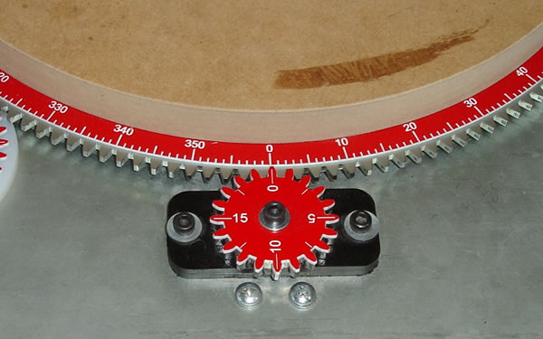
Improved indexing starts with the ability to know what degree the rotary table is at in the moment. Creating a custom degree wheel for the large gear on the rotary table solved the problem. Now it's easy to see what degree you are cutting at and verify your position.
You can find the desired angle by dividing 360º by your number of desired divisions. Knowing this number, you can rotate the rotary table to the correct degree location and make your cut. This make divisions such as 6 and 12 much easier since you can simple rotate to increments of 60º or 30º by reading the degree wheel. This is much easier than guessing where the crank handle should be to index the same locations.
The degree wheel is mounted between the waste board and the large rotary table gear as shown above. The waste board has been turned down to 12.25" in diameter.
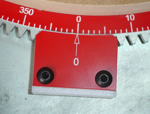
Two different styles of pointers are used to indicate your degrees depending on your level of accuracy required. A simple pointer and a Vernier Scale. They attach to the rotary table with magnets. This allows you to reset your zero point to increase the number if indexes if you wish.
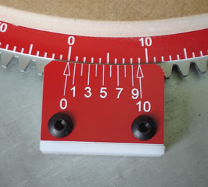
Using a Vernier scale style of pointer, it's easy to dial in 1/10 of a degree. For example, say you require 14 divisions on the rotary table. 360º divided by 14 is 25.7º. Using the Vernier scale, you simply rotate the table until the 0 on the Vernier scale aligns with the 25º mark on the degree wheel. Then you continue rotating the table until the line numbered 7 on the Vernier scale aligns with the 7th mark from 25º mark on the degree wheel. For more information on how to read a Vernier Scale I will refer you to Wiki.
In this picture, the Vernier scale is set to 25.7º. Notice the 7 on the Vernier scale is the only line that lines up with a one degree increment on the degree wheel.
Knowing the next increment is hard to do without doing math on the fly. That is error prone, so I feel a simple chart of the degree sequences for 2-20 divisions (Printable PDF version ) would be handy to have around.
Now I will not pretend to think or claim that this is a fast method of indexing. I will say it is an accurate method. The only other problem to account for is backlash in the rotary table gearing. I'm still working on a simple lock that will hold the table in place while you are making a cut. More to come later.
We can use the 160 tooth gear of the rotary table to our advantage. The 160 tooth gear allows us to index the gear in 2.25º increments. By turning 80 teeth you get 180º of movement. By turning 40 teeth you get 90º of movement or 4 divisions etc. Increments of 2, 4, 8 and 16 are pretty easy to do using the stock crank handle. But what if you are using the rotary table drive shaft? That accessory remove s the ability to use the crank handle as an indicator. Plus, counting the teeth that go on the large gear is not practical in some cases. Counting gears in your head could easily introduce error into our work.
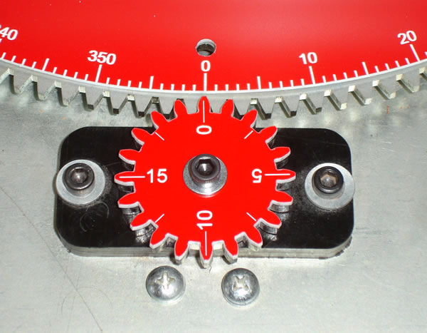
For quick indexing of specific locations, I developed "Tooth Counters". They are similar to threading dials on a metal lathe. They are simply gears that ride in the large gear and are specifically marked for quick indexing. There are two combinations that work well with the 160 tooth gear. The first is a 20 and the other is a 32 tooth gear.

The 20 tooth counter is mounted on the stock 20 tooth gear or could be mounted separately like the 32 tooth counter. It is engraved with 0, 5, 10, 15. The lines in between the numbers are useful too. The numbers simply correspond with the number of teeth . Using a number pattern you can easily index 6 different locations, 2, 4, 8, 16, 32 and 64. Using the teeth counters, you no longer have to know the degrees to advance, but simply follow a repeating pattern on the Tooth Counter gear to get your desired number of divisions.
This video (7mb) demonstrates the 20 tooth gear in action.
With the 32 tooth gear you can easily index 5 divisions, 5, 10, 20, 40 and 80. The 32 tooth gear mounts on a piece of Delrin that has magnets in the base. This allow you to place the dial anywhere you want to. You can also reset the dial to zero easily.

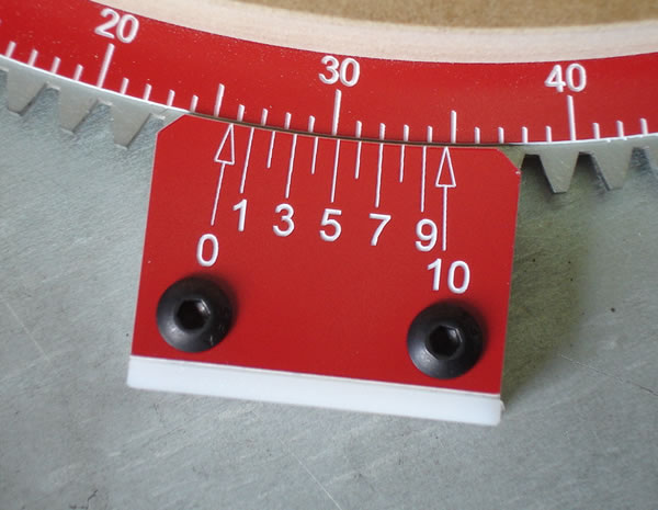
In this picture you can also see a pentagon marker that indicates 5 divisions. I also marked the large degree wheel with a Heptagon to indicate 7 divisions.
Here's a video of the 32 tooth gear in action(8mb). It shows making 5 divisions by moving 32 teeth at a time or 72 degrees. To physically count 32 teeth would be error prone if there was no visual aids or degree wheels to verify the location for every cut.
Using the above methods I think these divisions are easy to accomplish. In practice, my mind may change.
| Divisions | Degrees | Sequence |
|---|---|---|
| 2 | 180 | 0, 180 |
| 3 | 120 | 0 , 120 , 240 |
| 4 | 90 | Use 20 Tooth Counter - 0, 0, repeat |
| 5 | 72 | Use 32 Tooth Counter - 0, repeat |
| 6 | 60 | 0 , 60 , 120 , 180 , 240 , 300 |
| 7 | 51.249 | Use Heptagon marks on the division wheel |
| 8 | 45 | Use 20 Tooth Counter - 0 and repeat |
| 9 | 40 | 0 , 40 , 80 , 120 , 160 , 200 , 240 , 280 , 320 |
| 10 | 36 | Use 32 Tooth Counter - 0,16, repeat |
| 12 | 30 | 0 , 30 , 60 , 90 , 120 , 150 , 180 , 210 , 240 , 270
, 300 , 330 |
| 15 | 24 | 0 , 24 , 48 , 72 , 96 , 120 , 144 , 168 , 192 , 216
, 240 , 264 , 288 , 312 , 336 |
| 16 | 22.5 | Use 20 Tooth Counter - 0,10, repeat |
| 18 | 20 | 0 , 20 , 40 , 60 , 80 , 100 , 120 , 140 , 160 , 180
, 200 , 220 , 240 , 260 , 280 , 300 , 320 , 340 |
| 20 | 18 | Use 32 Tooth Counter - 0,8,16,24, repeat |
| 32 | 11.25 | Use 20 Tooth Counter - All of the numbers, repeat |
| 40 | 9 | Use 32 Tooth Counter - All of the numbers, repeat |
| 64 | 5.625 | Use 20 Tooth Counter - All of the numbers and lines,
repeat |
| 80 | 4.5 | Use 32 Tooth Counter - All of the numbers and lines,
repeat |
| 160 | 2.25 | Every Tooth |
This chart is also available in a printable PDF format
This is a work in progress. I still need to come up with a lock and fully test this out, but I'm extremely optimistic that it's a huge improvement over the stock rotary table.
Any question or comments feel free to contact me.